Category: STS - Source Transfer Switch / Model Name: STS for 3 Phase
|
Model
Number: STS3Phase

Download Brochure
Check Alarm Code
|
|
Features
|
- 3 Phase in - 3 Phase out / 50Amp to600Amp
|
- Increased power quality
|
- Easy monitoring all parameters on LCD display
|
- Fast microcontroller (32 mips)
|
- Power blackout protection
|
- Automatic static switching
|
- Remote monitoring of input power sources
|
- Easy statis and mechanical transfer between separate input sources
|
- Remote management of power events
|
- Power event logging
|
- Advanced RS232 communication features
|
- DRY contact alarm interface
|
- Password protected login system from remote site (time Access)
|
- 2 redundant power suppies for electronic boards (hot swappable)
|
- Easy front access to all components inside of the STS
|
- Second protection cover on live circuits which prevents electrical shock
|
- Input sources protected by fuses
|
- 3 positioned Maintenance bypass switch which prevent cross currents between input sources
|
- User adjustable parameters by entering a password
|
- Built in real time clock
|
- Alarm history (with date and time)
|
- Automatic transfer test from a remote site or using front panel
|
- Front panel Lamp test
|
- External emergency shutdown (EPO) input
|
- Hot plug construction during maintenance bypass
|
- High current output tolerance up to 1000%
|
- Temperature sensor inside the Cabinet
|
- Fast voltage black-out circuit
|
- Input phase balance and phase sequence fault detect circuit
|
- Adjustable Input source frequency lower/upper limits
|
|
|
|
|
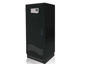
Product DescriptionsSTS Three Phase is a microprocessor controlled transfer switch, designed for automatic and manual switching between two AC power sources, with interruption to the load of less than 2 msecs with synchronized sources and of less than 12 msecs for unsynchronized sources.
STS utilizes SCRs connected in opposite parallel pairs (six pairs for 6 pole models ,eight pairs for 4 pole models) . Three or four pairs of SCRs are used to connect the AC load to the power supply input referred to as ìPREFERREDî, under normal conditions. The other three (of four) pairs of SCRs are on standby to transfer the load to the other power supply input referred to as ìALTERNATEî in case of a failure of the ìPREFERREDî input supply.
Source 1 and Source 2 supply inputs should come from two different AC sources with nominally identical voltages, phases and frequencies. The aim of the STS is uninterrupted transfer from one AC power supply to the other, in case of a fault in the ìPREFERREDî supply.
Before and during transfer from one source to the other, the operating conditions of the SCRs are carefully monitored to prevent crosscurrents between two sources. The break-before-make technique makes healthy and uninterrupted transfers possible.
During normal operation, ìPREFERREDî network supplies the load when both inputs are available. Selection of the ìPREFERREDî network, automatic re-transfer, retransfer delay, overload behavior of STS, alarm hold time, nonsynchronized transfer behavior, overload and transfer inhibit reset modes may be set by the user on the control panel of the unit.
Permitted voltage, phase difference and frequency tolerance are also adjustable by the service personnel on the control panel.
*§≈‘°¥Ÿý∑§π‘§ Source Transfer Switch (STS)
|
|